Research Facilities
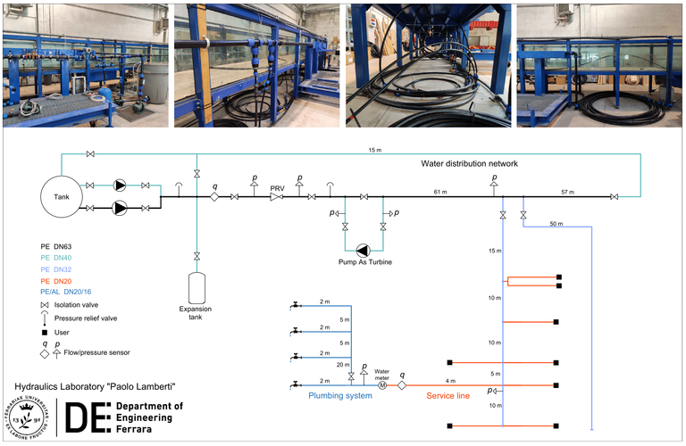
The test rig located in the Hydraulics Laboratory “Paolo Lamberti” of the Department of Engineering of the University of Ferrara (Italy) is aimed at studying the effects of transients induced by user’s activity on the components of water distribution networks, such as main lines, service lines, and plumbing systems. In greater detail, the test rig (shown below) reproduces part of a real water distribution network supplying a residential area and the plumbing system of a domestic user served.
In this part of the network, water is provided through a DN60 pipe of a total length of about 100 m, which supplies several domestic users and at the end of which a flow discharge valve is installed. Two DN32 polyethylene secondary lines (about 50 m long) branch off the DN60 line, one of which provides water to nine service lines. These are DN20 polyethylene pipes of a length of 2 to 5 meters. Specifically, one of these service lines supplies the plumbing system of a single-family two-story house, composed of DN20/16 pipelines of a total length of about 40 m. User’s plumbing system includes several domestic devices, spacing from knob taps to mixer taps, showers, and toilets.
The layout of the part of the real water distribution network, service lines, and the domestic user’s plumbing system considered was reproduced in our Hydraulics Laboratory by creating a hydraulic system fed from a tank with a capacity of about 1000 liters, downstream of which two centrifugal pumps allow water to be pressurized within the system. Pumps can work either individually or in parallel and their characteristics are the following:
- Pump P1: nominal flow rate of 1.25 L/s and nominal head of 47 m, with rated power of 1.85 kW (K55/50M provided by Dab Pumps®)
- Pump P2: nominal flow rate of 4.72 L/s and nominal head of 46 m, with rated power of 4.00 kW (K55/200T provided by Dab Pumps®)
The main pipeline was reproduced through a (100 m long) DN63 polyethylene pipeline branching off the pumping system, along which several devices were installed:
- An expansion vessel, protecting the pumping system against pressure fluctuations induced by manoeuvres on domestic devices;
- An electromagnetic flow meter, measuring the flow rate entering the system;
- A pressure reducing valve (PRV), allowing the modulation of the pressure head at which water is provided to the system;
The DN63 main pipeline also includes a bypass along which two parallel Pumps As Turbines (PATs) were installed. The activation of this bypass allows exploring and quantifying the energy recoverable in pressurized systems under different conditions of pressure head and water demand. Moreover, a DN40 polyethylene pipeline connected at the end of the main pipeline (and from which it is isolated by a valve) allows discharging water in the tank. This allows simulating non-ordinary discharge conditions due to pipeline washing operations or fire flows and investigating their effects.
Two DN32 polyethylene pipelines of a length of about 50 m each and nine (4 m long) DN20 branches were used to reproduce the two secondary lines and the service lines supplied by one of these, respectively. In the user’s service line reproduced, a mechanical water meter and an electromagnetic flow meter for domestic inflow monitoring were included, whereas a simplified scheme of the case-study user’s plumbing system was realized, featuring DN20/16 PEX-AL-PEX pipelines and four discharge points representing devices placed in different locations of the house (front yard, ground floor, first floor, and backyard). These devices discharge water in the tank, thus closing the hydraulic system developed.
Pressure monitoring can be conducted at several points of the hydraulic system: at three sections on the DN63 main line, i.e. downstream the pumping system, downstream the PRV, and in proximity of the branching of the two DN32 secondary lines; at one section of one of the DN32 lines, i.e. in proximity of the case-study user’s service line; and downstream the case-study user’s service line, i.e. in the proximity of the mechanical water meter. Flow monitoring can also be conducted, with regard to a section immediately downstream the pumping system and at the case-study user’s water inlet point. The simultaneous sampling of pressure –through five pressure transducers installable at pressure measurement sections– and flow rate –through two electromagnetic flow meters– is performable at high frequency (101–103 Hz) through a series of modules National Instruments® and the acquisition is managed with the programming software LabVIEW®.